

Ned McIntosh
-
Posts
12 -
Joined
-
Last visited
Everything posted by Ned McIntosh
-
The Longplate- option for all rigs.
Ned McIntosh replied to Peter Abraham's topic in Camera Stage/Donkey Box
Thanks Peter. A genuine VCT-14U weighs 29.6 ounces (0.84Kg) so the Longplate is lighter. -
The Longplate- option for all rigs.
Ned McIntosh replied to Peter Abraham's topic in Camera Stage/Donkey Box
"Salierient"?...why they're positively sadagerous words! Peter, would this be too long for the Pilot HD stage? I have a cage-rig for the GH4 and the rig normally uses the Sony VCT-14U plate, but that adds rather more weight than I'd like, plus there is the issue of developing play in the plate with the cage-rig mounted. One of these would perfectly replace the VCT-14, make finding the CofG easy and allow wider spacing of mounting-screwson the Pilot HD stage, but the length has me a bit concerned. (I'm assuming the long plate weighs less than the VCT-14, but I might well be wrong.) -
A further thought. As a retired skydiver, I know the manufacturers of sports parachuting harness-and-container systems produce products which are somewhat analogous to a vest. They are worn several times a day, for periods of possibly as long as half an hour at a time, have to be durable and rugged to survive years of use yet remain functional and low-maintenance and (most importantly) comfortable for the user. There are several such manufacturers in the USA and a phone call to them might uncover some useful ideas for types of foam which work well for these requirements. If this idea has merit, I can look in the latest "Para-Gear" catalogue for the names of the companies. I don't have the catalogue with me at the moment but I can lay my hands on a copy.
-
Would a laminate of 1 piece 1/2" soft foam (fast recovery) and 1 piece 1/2" harder foam (slow recovery) be worth a try? I've seen a triple-laminate of three different recovery-rate foams used for custom seat-cushions for a home-built aircraft, and I also note Chris Fawcett is using a three-layer foam approach for the Exo-Vest. Chris's foam are three separate pieces and designed to be reversed, whereas the seat-cushion foam was cemented together, frozen in liquid Notrogen and cut precisely, clean as CNC or laser-cutting. If nothing else this would allow the user to choose which side of the foam felt better or worked better for him or her. It might be worth talking to some of the custom auto upholsterers, too; those guys know about all kinds of foam and I've always found them to be helpful. Just a few thoughts.
-
Cheap SDI to HDMI converter
Ned McIntosh replied to Zoran Vincic's topic in Video Assist and Video Accessories
Hi Zoran, you're quite right. I opened mine up and found the same 1117 regulator and 25 volt electrolytic capacitors. So I can feed it directly from the DC output on the Pilot stage using the IDX V-vlock battery. The only diffference was mine had 4 screws holding down the circuit-board. For the money they're quite useful, but they wouldn't survive a lot of abuse. -
Zoran, mine is probably the exact same circuit-board in a very slightly different enclosure. I'll open it up and check it out. You may have just simplified my rig!
-
Cheap SDI to HDMI converter
Ned McIntosh replied to Zoran Vincic's topic in Video Assist and Video Accessories
Oops, just realised this thread is about a converter that goes the other way (SDI toHDMI). I really should get one of these as well and see if it has the same specs for input etc. You guys have given me some good ideas! -
Cheap SDI to HDMI converter
Ned McIntosh replied to Zoran Vincic's topic in Video Assist and Video Accessories
Charles, my converter supports HDMI Input timings 480i@59.94, 576i, 720p@50/59.96/60, 1080i@50/59.94/60, 1080p@ 23.98/24/25/29.97/30/50/59.94 and 60. The maximum output bit-rate is 2.970Gbps. As I mostly work in TV and video this unit works fine for me - all it has to do is drive the HS/SD monitor on the Steadicam Pilot or turn HDMI out of my GH4 into HD-SDI for display or onwards transmission. If I needed more versatility I'd definitely be looking at Decimators, AJA or Blackmagic Design hardware. We have some of each where I (occasionally) work so I could check them out and see which seem to be the most durable and capable. Mine is very similar externally to the one Zoran photographed but I haven't opened it up yet to peek inside. I wouldn't be surprised it it wasn't the exact same unit re-packaged by the wholesaler. Hopefully they used four screws to hold the pcb down! He's right about the BNC connector too - looks like "no expense was spared to keep the cost down". -
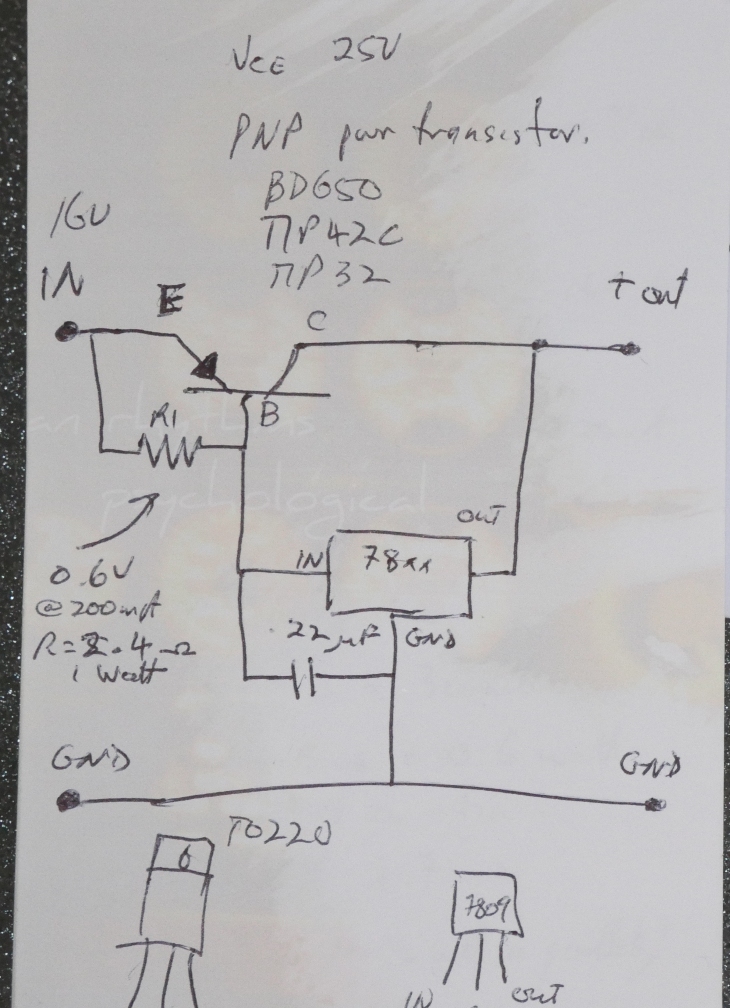
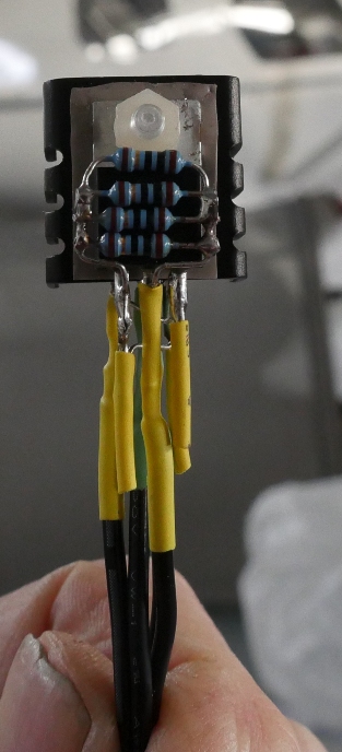
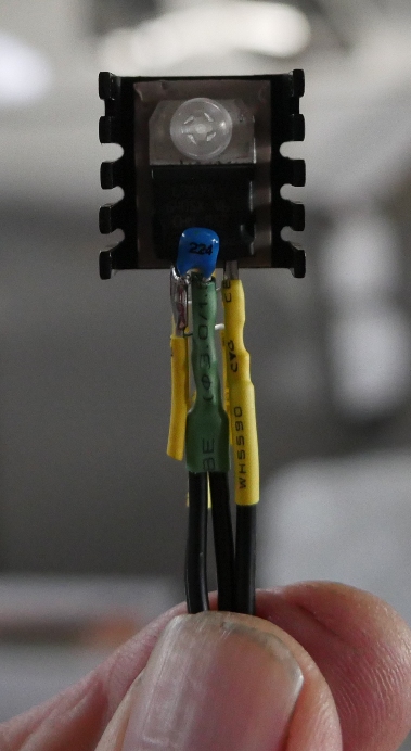
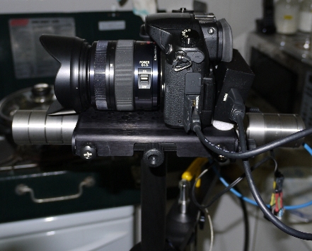
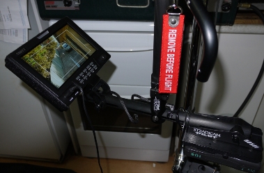
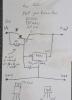
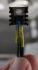
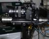
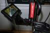
Apologies for dredging up an old thread, but here's my way of increasing the current out of a 3-terminal voltage regulator to drive an HDMI-SDI converter on my Steadicam Pilot HD rig with the Panasonic GH4. (With different connectors it could be used on pretty much any model of Steadicam, or for multiple other uses.) Basically, you add a pass-transistor, with the output-terminal of the regulator connected to the output (the Collector) of the transistor, and solder a resistor between the Base and Emitter of the transistor, which then goes to the input of the regulator. Here's the circuit-diagram:- The voltage regulator is any of the 78xx series positive 3-pin voltage regulators, the pass-transistor is a Silicon PNP power transistor. I used the very common TIP32 in a TO-220 package, same as the regulator, so they could share a common heat-sink. You need to work out the value of the resistor (easy enough), and the capacitor is a 0.22microFarad cap for stability at the input of the voltage regulator (it's not very clear on the diagram). All this should cost less than $5, which is pretty cheap in the world of Steadicam! Here's how it works: Power in (16.2 volts from your IDX battery, for example) is applied to the Emitter of the transistor and also to the 2.5 Ohm resistor (which I made by putting four 10-Ohm 1/2 Watt resistors in parallel). The other end of the resistor is connected to the Base terminal of the transistor and to the Input terminal of the voltage regulator. As the current flows into the voltage regulator, a voltage is developed across the resistor. You want this voltage to be 0.6 Volts to forward-bias ("turn on") the Base-Emitter junction of the transistor so it conducts and allows current to pass through it. We'll get to the value of the resistor shortly. Now, here's the clever bit. Because the output terminal of the regulator is soldered directly to the Collector (output) of the transistor, the voltage at the Collector must be the same as the output voltage of the regulator. In other words, as the transistor is turned on, the excess voltage will be dissipated across the Emitter-Collector circuit of the power transistor. Okay, how do you work out the value of the resistor? Measure the current drawn by whatever device you intend to drive at the regulated voltage. My HDMI-SDI converter draws 200mA at 9 volts with HDMI in and driving an SDI monitor, so I needed a resistor that developed a voltage of 0.6 volts at 200mA. Ohms law says this is 3 Ohms, but resistors come in a preferred series and the closest value to 3 Ohms is a 2.7 Ohm resistor. Unfortunately I couldn't find a 1W 2.7 Ohm metal-film resistor, so I made a 2.5 Ohm 2 Watt resistor by putting four 10 Ohm 1/2 watt resistors in parallel which becomes a 2.5 Ohm 2Watt resistor...perfect! The wattage is also important because you don't want the resistors to burn out! Power is current squared multiplied by resistance, so 200mA squared multiplied by 2.5 is 0.1 Watts. My 2W resistor should handle it. Now the beauty of this simple but useful circuit is the power transistor can handle far higher current and dissipate far more heat than the regulator on its own. Your device can draw a few amps without any problems, as long as you can get rid of the heat generated. Power transistors are designed to do this all day long, but you have to get rid of the heat, perhaps several watts or more...that's where the "heat-sink" comes in. Both the regulator and transistor are mounted, back-to-back using adhesive heat-transfer tape, to a single TO-220 heat-sink. We just let the entire affair hang out in the air, where natural airflow will allow the heat-sink to do what it does best - get rid of heat. This circuit should work in a 105 deg F day in Abu Dhabi, Arizona (or the Australian outback) as well as it does in a -40 F day in the midst of a Candian winter, or a shoot in the polar regions. So, a few simple, cheap components, a little soldering, some assembly and now you have an adapter lead from your Steadicam Pilot power outlet on the rear of the stage to drive whatever you like. My HDMI-SDI converter was rated 5-12VDC input and I didn't fancy stuffing a raw 16 volts into it. I made a 5-volt lead, a 9-volt lead and a 12-volt lead. The regulator will "drop-out" when the input voltage is about 2 volts above the output voltage, so with the 12-volt lead when the IDX battery drops to 14 volts, the 12-volt regulator shuts down. Just replace it with the 9-volt lead and keep working until the IDX battery itself is discharged. The 5-volt unit runs hotter than the other two, and I prefer to run either 9 or 12 volts into the converter anyway. Keeping this circuit simple is the key to reliability. The power transistor isn't a high-gain device so I haven't bothered adding RF bypassing with ceramic capacitors. If RF energy from handheld radios, base-stations etc causes problems, add a ceramic capacitor between output and earth on the regulator. The capacitor needs to have a low impedance at the RF frequency in use (you use the formula for calculating capacitve reactance to work that out.) Less than 10 Ohms should do. Here are a few photos showing the appearance of the completed unit:- This is the Pass-Transistor side with the resistors visible, and this is the other side with the voltage-regulator and little capacitor visible. I have built 20-Amp variable power supplies using the same basic circuit with an adjustable voltage-regulator so I know this circuit works and works well. Once you have built it, double check you have the polarity of the input and output connectors correct before you go applying any voltage to the input. 78xx voltage regulators HATE reverse polarity! How does the Pilot HD stage look with the GH4 and converter rigged? Like this:- The stage has plenty of fore-and-aft adjustment, you can see how many weights are needed with the GH4 to properly load up the arm, and the regulator is hangng down behind the rear weights (somewhat out of focus). The HDMI-SDI converter is attached right behind the GH4 with Velcro "sticky-dots" and tilts back a little...a minor issue. The converter is one of the cheap "generics" available on eBay for less than $50. Light, small and well-matched to the Pilot HD, it drives the SWIT monitor nicely. (Photo below)

-
With my Panasonic GH4 and the 12-35mm lens and hood, the CoG of the camera is behind the gimbal by about 1/4 inch (say 6mm or so). Once the drop-time is correct, the dynamic balance is good enough. Bear in mind that due to its construction the Merlin 2 can't achieve a full-rotation whip-pan anyway. If it falls "flat" when you do your drop-time test, you're good to go.
-
Hi everyone, a quick note to say "G'day" and briefly introduce myself. I have to admit to 23 years in broadcast television, beginning in 1993 when I left the merchant marine (Radio Officer) and entered TV as a freelance cameraman and sound-recordist. That was back in the Betacam SP days - boy those things were shoulder-breakers! My rig spent almost all of its time "on the sticks" shooting sports with a 5" studio viewfinder on top. Since then I've added master-control, presentation-switching, microwave links and satellite uplinks to my portfolio, but I've always liked pointing a camera at something, which I have been doing (on and off) since the early 1970s. These days I wield a Panasonic GH4 (working in HD not 4K), coupled to my extensive collection of old Minolta Rokkor 35mm glass via a Metabones Speed Booster. My steadicam gear consists of a Merlin 2, Merlin arm and vest, a spare Pilot arm, and a complete Pilot HD system. Like a lot of freelancers I've built dollies out of plywood and track out of PVC pressure-pipe, laboured to set them up for a ten-second shot and envied the grace and fluidity of Steadam work but was unable to afford the rigs which cameras of the day required. Now cameras are smaller, the rigs are far more affordable and I decided I had to "get on the bus". In my current TV work I get to meet Steadicam operators on most jobs, so I can pick their brains for hints and tips and watch the way they work. These guys are mostly using the Shadow, a nice rig but way too big for what I am doing. I am very pleased to see the names of some of the acknowledged Steadicam Masters on the forum. When these people post, a wise man reads, absorbs and understands. I feel privileged to be here and although I may not have much to say, I'll be gleaning as much as I can from the collective wisdom of the forum and its members.
-
Hi Andy, I just removed my Merlin 2 gimbal to see if there is a way. From what I see, the small tongue that locks into the groove in screw-housing on the stage will completely retract if you apply sufficient pressure to the small button in the guide. That's the button you have to press to allow the guide to screw in or out. Provided you can get the button down below the surface of the guide, that should retract the tongue enough to allow the thread to start unscrewing. As far as I can see, the Merlin 2 gimbal cannot be disassembled - once the factory build it, it's fixed for the life of the unit. The tiny pins for each bearing appear to be press-fitted and the ends swaged slightly into place.