


GregBubb
-
Posts
30 -
Joined
-
Last visited
-
Days Won
4
About GregBubb

Recent Profile Visitors
1,043 profile views


-
I have will have available a very limited supply of 2 mm thick, clear soda lime glass with a 2 sided AR coating (anti reflective) that will fit and is captive in the Small hd 7" monitor with the removable bezel. You know its removal bezel if you have the four screws on the front face plate, one each corner. Cost per glass is $28.00 Expected delivery June 1 Finished size: 5.98" x 3.75" x .078" Please email me if you need one. GBubb@aol.com Greg
-
play within the bayonet connection
GregBubb replied to JensSchroeder's topic in Camera Stage/Donkey Box
There are multiple issues that I think are being discussed here. Both of which I am very familiar with. Pro manufactured two different height knurled locking rings. The first locking rings are shorter in height by about .040" than the current knurled locking ring. These rings were on all sleds they made for about the first 6-7 years. These are the two rings that hold the center post to the upper camera platform and lower aluminum housing. About eight or nine years ago, Pro increased that height which prevented original XCS posts with Pro mounts to fit firmly together. I then immediately redesigned the mount so that is no longer an issue and will never be an issue. When Pro went to the thicker mount, they completely stopped making the older mount for all their owners and only provide the newer version. There are really three options for a permanent fix if you damage your older knurled rings. The best option for resale is obviously to change the post ends in the 2" carbon fiber post. The second option would be to take your knurled ring to a machinist and shave off .040". I would take .020" per side -0/+.005. The last option is a .050" spacer that you can actually stick inside the knurled ring which allows a tight fit. I think the second issue is one that I have seen more than a few dozen times and can only assume Pro is aware of it. What a few other operators here are thinking may be related to the first issue. It sounds like James is speaking of this very thing. For those who are unaware, when you mate a Pro post to the upper and lower housing the aluminum post doesn't actually touch the aluminum housing of the mating component. The conical pins actually are designed to carry the load, and there is approximately a .010" gap between the two aluminum components. What I have seen and measured is an occurrence that happens when one or two stainless steel pins in the upper camera platform (most likely the culprit), or lower aluminum housing gets pressed into its own housing causing a scenario like a three legged barstool with one short leg. The end result of this will cause the camera platform to shift under weight resulting not only in movement, but your sled will not maintain balance. This movement most of the time cannot be seen. It is moving in thousandths of an inch and is almost impossible to see, but it can be measured. This small amount one may think is insignificant, but when you are talking 20 and 30 lb. plus cameras it will have your sled sitting at a 45 degree angle or more. Here is a quick test to show how little a few thousandths of an inch will throw off a sled. Left to right balance adjustment is a 10-32 threaded shaft. One full revolution moves the camera platform .031". If you balanced your sled and moved your inching knob 45 degrees, you just moved it .0077". If you move it only 22.5 degrees, that is .0038". You can see how your sled reacts to balance when you turn your inching knob 22.5 degrees after it is perfectly balanced. It very difficult to see .004" movement, other things are flexing that much already with a 30 pound camera. Stay level. Greg -
Based on shear strength and flexing the interchangeable tubes don't need to be solid. I keep the weight down as far as I can safely can go and still ensure the shear strength of the product with no bending. To add my two cents on low mode and arm length, I try to clearly indicate that in low mode your physical arm length is the limiting factor to being able to push down the mechanical arms full length while using the medium or long post in the swivel. I am assuming most operators operate with their hand on the gimbal here. I cover this on the XCS web page in more detail. Achieving the additional low mode height you benefit from while using the Mid Arm Swivel (MAS), while not having to push down on ones mechanical arm keeps the sled away from your body, mainly your legs and still allows the full up down boom range for possible lower starting or end heights, already mentioned above. But this is only one of the flexible options it offers me. I think in the end shots achieved by other operators tell the story and they may have different requirements in everyday use of the MAS. Most of the time for me it's not the high low extremes. There are a few ways to achieve the different performance characteristics that the MAS achieves. But no other method I have seen can achieve all its capabilities without changing the sled center post length, gimbal handle or adding an extreme low/high bracket which changes the sled dynamics. To me it's all about sled performance, flexibility, speed, safety. Walters drop down socket block may solve a different issue for some with another manufacturers product but it sounds like when added to your vest, you will be adding another 3" plus in height to your arm post to bring the height back up to where it started. 3" of drop down is a rough estimate going off memory from 4 weeks ago. I am not here to sell a product, I am just clarifying what this product can and does do based on using it for many years. Greg
-
Thank you Tom and also to another operator pointing me to a few videos on line. I had a slightly different mental image of the LED display array than it actually is. There are 4 vertical rows of LED’s that stretch out 53 rows horizontally. The moving bar is indicated by a four wide by four high moving array. They do indeed move one vertical row at a time. Thank you Wolfgang Troscher for posting the You Tube video. I did read the manual late last night and it brought to mind a few questions. I just wanted to be clear on what the visual display is actually representing. Now that I have a clearer understanding I can speak a bit more intelligently to the details stated in the Tiffen operations manual. That will have to be later, have to run. Greg
-
Steve thank you for your response. Do you own one of these units, or are you from Tiffen? So, 53 LEDs make up the 2.25” wide array with 4 LED segments that make up the traveling indicator that are illuminated at any one time as they moving across the display. Understood thanks. I’m still unclear about a few things, if you or anyone else can clear chime in to help me understand. If the total level range of the WHM-BG LED’s can reading +/- 12 degrees at its furthest left to right travel, is that range user programmable? Any idea of the speed of the response time? Can I select WHG-BG to only read +/-2 degrees over the +/- 24.5 line segments LED segments from center? 53 - 4 (zeroed center segments) = 49/2 = 24.5 LED per side, I knew that collage degree would come in handy. I will to round it to 52 LED segments total on the display for my next question, this gives me twelve 4 LED segments per side from the Zero-ed centered point. If any 4 LED’s segments make up the traveling visual marker and there is always four segments illuminated, can I assume that they light up one ¼ of a line segment at a time as you go off level? And it doesn’t jump to the next full four segments as the segments travel across screen? If only I had a video of it traveling slowly across the screen it would answer a few of questions. Greg
-
I have never played with the WHM-BG device. Reviewing the manual on Tiffin’s web page it appears that there are a series of LED indicators that illuminate across the display which indicates off level, or off your ZERO-ed level setting is that correct? There is a center LED indicator that is a different color than the rest that shows your “leveled setting” or what I would call ZERO-ed setting. Is that correct? Each LED at is goes across the display illuminates as you hit a preset “off level” threshold? It appears that there is a user selectable setting range of +/- 2 or 3 or 4 or 6 or 12 degrees. Is that lets say 2 degrees cover the full +/- range of the LED’s ? Or does each LED that illuminates as you increasingly go off axis increase from Zero-ed setting to 2 degrees than 3 degrees etc. up to 12 degrees being the last LED? Lastly if the LED indicator covers a user defined range, let’s say +/-2 degrees from center to left or center to right, how many LED’s are used to cover the full range left to right and center on the display 5, 11 , 21? Anyone know these answers? Greg
-
Stresses are understood and parts engineered to specification. The additional stress that is added on the interchangeable arm posts and mating swivel connection points are understood with current camera/sled weights and arm limitations. That is one reason why these are all very high tolerance ground posts and mating connection points in the swivel. It is critically important to lock both screws and make sure you have the interchangeable posts fully captured at both ends. The bearings we use are also tolerance for the weight applied. The connections points to the arm are the same. I have flown a 3D rig on the 6” post in excess of this weight. 75 lbs. this is more than any arm can hold up. Greg
-
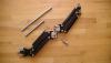
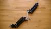
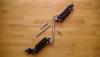
The Extendable Mid Arm Swivel. This is why I designed it. I wanted to be able to quickly and safely place a camera very high and low while not having to extend my center post at all or use a super post. Most operators understand or do it unconsciously that on most common sled designs when flying a 34 lb camera package (my common avg weight) there is roughly about a 3:1 ratio when telescoping your center posts to achieve a higher or lower camera lens position. Or another way to think about it is for every 3 inches of inner post extension you get about 1 inch higher or lower with the lens. We also understand the effects on performance a longer center post has on your operating which may include slower sled response, additional vibration it may induce and whether or not you have any center post left to extend to get those few inches you are looking for. One can use an arm post to get a camera higher or lower by 3, 5, possibly 8” or more and I have done that over my career. I have also bent and saved the sled and camera more than once doing that. I feel once you start lifting a camera 5 plus inches on arm post especially tube style arm posts it is a matter of when it will bend or snap, not if. Working around crew and actors safety is number to me at all times not matter what I am doing. So I designed the Extendable Mid Arm Swivel to fill my needs a while ago. In addition we are not just about the ability to offset 4-6 inches, we are talking up to 12” lengths safely. There are 3 interchangeable posts in the Extendable Mid Arm Swivel that will become the standard interchangeable post lengths. Currently I have 4 post lengths for the first batch and may continue with 4 on the second run. But for now I feel these 3 lengths will work nicely. 1) 2.8” for no extension like your standard mid arm block 2) 6” for high or low mode work. 3) 12” for high or low mode, full length not needed. They are held in position and removed with a turn of a single 8-32 SHCS on each block. Here is what it does for the operator and what I was demonstrating at the Stabilizer Expo. When changing the swivel posts half the time I would show the operator how to do it while still suited up with the arm attached to their body which is very quick. Other times I would just set the arm down so they could see what I was doing. 1) Without changing the arm post or center post length operators could quickly (15 sec- 1min) take and raise the camera in high mode by 1- 14” higher from its standard highest point. By doing this you have of course raised the lowest point the arm goes by that same amount. 2) Again without changing the arm post, flip your gimbal handle over and use a J bracket or change your center post length. Operators could quickly (15 sec- 1min) take and lower the camera in low mode by 3-4” without have to push down on the arm at all to achieve that lowest lens height you would achieve by pushing down on the arm. I still can have the full range of boom up/down and no concerns of hitting the lower portion of the arm while walking/running. As an operator I never would allow myself to hit the lower portion of the arm during any shot previous to this device. You as an operator would only go as low as you could with the lens height to prevent this from happening unconsciously. Now you do even have to push down on the arm, you could of course if you wanted. Pushing down on any arm of course draws it closer to your body which also can inhibit your movements, not anymore. Initially I was hoping for a lower mode lens height and had plenty of interchangeable post to do it. But your physical hand can only reach so low before you can’t touch the gimbal any longer. 3) There are no performance effects on the arm. It feels and performs exactly as your arm currently would without the swivel. 4) Currently it is made to fit the pro arm only, both versions. There are two other live television steadicam operators that have been using my Extendable Mid Arm Swivel since the Academy Awards show this year. With a handful of other ops that all worked together at the same time on the show. The eye level to extreme high mode shot achieved by Tore L. was completely un-steadicam like in his ability to keep it booming up higher and higher to the end of his take he was asked to do. To answer Robert’s statement, the live TV op’s are being paid extra for not only the Swivel but also a bump in operating rate. You would have to contact him for specifics, I seem to remember somewhere in the $200 a day for the swivel and $15. Per hr additional. The rest of us operators well? This device is not for everyone like anything I design and manufacturer, it starts out selfishly for me. It would have never have been brought to market and have been able to keep it a low profile item for a long time. It was at the Academy Awards Technical Achievement ceremony that I was informed by Tore that he was positive Garrett Brown had observed it. I immediately filed for the Utility patent. After all Garrett knows what he is looking at and I can only assume that he could see what Tore was able achieve. Garret’s observation is speculation on my part only, but I cannot take a chance. I don’t make arms, this is why I kept it under wraps. Any arm manufacture I feel would have immediately made this a standard design on the arm, of course patented the design and offered it as option or standard item. That leads into questions I received at the expo, “if it will be available for other arms”? I will have to wait and see if the market demand is there. The costs are over twice as expensive to design and build an asymmetrical Extendable Mid Arm Swivel like the model CP 2, 3 arms Vs arms that have a symmetrical design. I addition arm manufactures have not kept a standard size in this mid arm swivel section of the arm. Greg
-
1
-
With today’s Lithium batteries you have you two basic cell types, Polymer and Ion. Both deliver the high current you need for the HD and film cameras we run. They both have similar performance and temperature curves. I have owned, tested and used Lithium packs for over 12 years and both cell types have just kept improving and work well. Extreme hot and cold you should be a bit more cautious. Engineers may say by the numbers that Ion cells can deliver a higher current at startup due to lower internal cell impendence, but with the current capability of both types of cells I find it’s indistinguishable between battery packs with the wattage we run and the amount of current batteries can provide. 90, 120, 160, 190, 235 watt hr battery pack being the most common standard sizes. Using a larger watt hr pack will extend the life of that battery pack under similar current loads since they deplete at the same rate. So if you are buying a 90 watt battery pack Vs. a 150 watt pack and putting an 8 amp constant load on it for example, the 90 watt pack will of course reach the end of its useful battery life sooner over the life of the battery Vs. 150 watt hr pack that may cost $40. more and weight additionally 4 ounces more but may give you 6 months longer run time over its battery life in addition to its initial longer run times. I have gone from three 90’s watt packs 10+ years ago, to two- 160’s 5 years ago, and to two 235watt packs today. Buy the way two 235 watt packs weight 1-2 ounces less than three A/B 90 watt hr packs with a total increase in capacity of about 74%. Additionally you will notice that some resellers are selling 14.4 Vs. 14.8 nominal voltage packs that allows them to give you a 10-15 watt higher output rating which is negligible (a numbers game) to steadicam, ONLY if you equipment can handle the higher voltage output of these packs. It only gives you an appearance of higher capacity which operators may think they are getting a longer run times, they are not. Because the camera will run below the batteries low voltage rating. Listed are some well known performance factors by battery manufactures but I feel sometimes misunderstood by the end user. 1) First both types of Lithium cells and will deplete at a very similar rate when used similarly. 2) Both cell types will lose performance and deplete over time whether or not they are used. 3) Both cell types will typically lose 20-30% of the current load capacity after 18-20 months or 100 cycles when high current loading a battery pack, slightly more cycles when not. High current loads are considered power draws that are greater than 60% of the battery wattage rating. Or just about every battery we use on a sled under 150 watts if you run two batteries and power the camera. 4) Different battery wattages have different thermal fuse ratings. Typically between 10.25- 15 amps. This is important as you draw down the battery voltage when using it and your battery ages. The lower the voltage output of the battery the high the current (Amp) draw it has on your battery pack. So as your battery ages it pulls more current (amperage) at lower voltages to run that camera, you will reach that thermal fuse limit sooner. 5) That most all reputable battery suppliers in our market are using reputable cell manufacturers of equal quality. So that name brand pack when opened up might have that same Samsung, Sanyo, Saft cell and you can expect similar performance. These companies are all completing for the same market. 2/3 of the packs I take apart from different resellers are using the exact same cell. And the price varies from each company. I have tested a few off brands and find they perform as well or better then the two major brands on the market. 6) We all have different tolerance to battery packs at the end of their useful life. I can only speak for myself here. When my batteries are only lasting 20 minutes before I have to change them it’s time for new batteries. Others may change sooner, some may allow even shorter runtimes. So battery end of life is very subjective. What is missing out of this equation of battery runtimes and performance (ability to deliver power) on a sled is the most important, least talked about and least understood subject. Power delivery though the sled. This is where two identical battery packs under the same current load using the same camera can have two different run times, power outputs and cycle life. This comes down to three things. Proper power wire gauging through your sled including power cables to camera. Connector sizes in your sled, and is there an active battery management system, or is it just you managing/monitoring the packs yourself. Wire : The length of the power wire run through the sled system is or should be an important consideration for all. Most who know me understand I could go into great detail on these points but ones needs only to visit a web page with a DC voltage loss calculator and input the few basic parameters to get the big picture on power loss over a give wire length. It will ask a few basics you, fill in the blanks. A) AC or DC current B) Nominal voltage- input the lowest voltage you run your batteries down to. 12.5, 13.0, 13.5 C) Wire length. Remember this is a loop. Voltage travels from battery to camera, back to battery. A standard XCS/Pro sled wire run would be around 10 feet for a god estimate of length. 3 and 4 stage posts add the additional length of the post stages, times 2 D) Wire type copper or tinned copper I would guess most are using with standard strand count. E) Wire gauge most makers are using 22 Awg wire and one or two in a multi conductor scenario running parallel. Using two 22 Awg wire doesn’t equal 19 Awg. In a perfect world in the lab with no current draw or minimal, not true in operation. One only needs to Ohm out each conductor to see that difference. These on line calculators will tell you the voltage loss in your system due to the wire gauge/length you have. I would say that on average you will see a 1.5 volt loss from top to bottom on many systems, but not all. So that may be 20% of your battery life gone due to poor wiring/connector standards when your sled is under load. Lastly battery management. This as well is critical to battery performance and cycle life. In all current sled designs except for one manufacturer, they combine two or three battery packs in parallel or series and sometimes both with no monitoring of the individual capability of each battery pack. I am not talking about reading battery voltages, rather an active battery capacity monitoring system. When battery packs are linked together in 12 or 24 Vdc mode they are only as good as the weakest battery pack or cell in any single pack or a wire that has a higher resistance, it all comes into play. There is far more intelligent full proof method. Using this old hard wired method which is still a standard way to handle batteries is why one should not run old and new battery packs together at the same time. You’re depleting the performance of the overall battery system and runtimes. Not even considering the increased resistance in the sled wiring due to heat buildup due to a weaker battery pack. If you what the best performance out of your packs and don’t have proper battery management electronics use packs of the same cycles or age, don’t mix one old with one new. I am not advocating any specific battery supplier just keep an open mind on what is available. Sorry for the long post. Heavily edited to keep it this short. GregWith today’s Lithium batteries you have you two basic cell types, Polymer and Ion. Both deliver the high current you need for the HD and film cameras we run. They both have similar performance and temperature curves. I have owned, tested and used Lithium packs for over 12 years and both cell types have just kept improving and work well. Extreme hot and cold you should be a bit more cautious. Engineers may say by the numbers that Ion cells can deliver a higher current at startup due to lower internal cell impendence, but with the current capability of both types of cells I find it’s indistinguishable between battery packs with the wattage we run and the amount of current batteries can provide. 90, 120, 160, 190, 235 watt hr battery pack being the most common standard sizes. Using a larger watt hr pack will extend the life of that battery pack under similar current loads since they deplete at the same rate. So if you are buying a 90 watt battery pack Vs. a 150 watt pack and putting an 8 amp constant load on it for example, the 90 watt pack will of course reach the end of its useful battery life sooner over the life of the battery Vs. 150 watt hr pack that may cost $40. more and weight additionally 4 ounces more but may give you 6 months longer run time over its battery life in addition to its initial longer run times. I have gone from three 90’s watt packs 10+ years ago, to two- 160’s 5 years ago, and to two 235watt packs today. Buy the way two 235 watt packs weight 1-2 ounces less than three A/B 90 watt hr packs with a total increase in capacity of about 74% Additionally you will notice that some resellers are selling 14.4 Vs. 14.8 nominal voltage packs that allows them to give you a 10-15 watt higher output rating which is negligible (a numbers game) to steadicam, ONLY if you equipment can handle the higher voltage output of these packs. It only gives you an appearance of higher capacity which operators may think they are getting a longer run times, they are not. Because the camera will run below the batteries low voltage rating. Listed are some well known performance factors by battery manufactures but I feel sometimes misunderstood by the end user. 1) First both types of Lithium cells and will deplete at a very similar rate when used similarly. 2) Both cell types will lose performance and deplete over time whether or not they are used. 3) Both cell types will typically lose 20-30% of the current load capacity after 18-20 months or 100 cycles when high current loading a battery pack, slightly more cycles when not. High current loads are considered power draws that are greater than 60% of the battery wattage rating. Or just about every battery we use on a sled under 150 watts if you run two batteries and power the camera. 4) Different battery wattages have different thermal fuse ratings. Typically between 10.25- 15 amps. This is important as you draw down the battery voltage when using it and your battery ages. The lower the voltage output of the battery the high the current (Amp) draw it has on your battery pack. So as your battery ages it pulls more current (amperage) at lower voltages to run that camera, you will reach that thermal fuse limit sooner. 5) That most all reputable battery suppliers in our market are using reputable cell manufacturers of equal quality. So that name brand pack when opened up might have that same Samsung, Sanyo, Saft cell and you can expect similar performance. These companies are all completing for the same market. 2/3 of the packs I take apart from different resellers are using the exact same cell. And the price varies from each company. I have tested a few off brands and find they perform as well or better then the two major brands on the market. 6) We all have different tolerance to battery packs at the end of their useful life. I can only speak for myself here. When my batteries are only lasting 20 minutes before I have to change them it’s time for new batteries. Others may change sooner, some may allow even shorter runtimes. So battery end of life is very subjective. What is missing out of this equation of battery runtimes and performance (ability to deliver power) on a sled is the most important, least talked about and least understood subject. Power delivery though the sled. This is where two identical battery packs under the same current load using the same camera can have two different run times, power outputs and cycle life. This comes down to three things. Proper power wire gauging through your sled including power cables to camera. Connector sizes in your sled, and is there an active battery management system, or is it just you managing/monitoring the packs yourself. Wire : The length of the power wire run through the sled system is or should be an important consideration for all. Most who know me understand I could go into great detail on these points but ones needs only to visit a web page with a DC voltage loss calculator and input the few basic parameters to get the big picture on power loss over a give wire length. It will ask a few basics you fill in the blanks. A) AC or DC current B) Nominal voltage- input the lowest voltage you run your batteries down to. 12.5, 13.0, 13.5 C) Wire length. Remember this is a loop. Voltage travels from battery to camera, back to battery. A standard XCS/Pro sled wire run would be around 10 feet for a god estimate of length. 3 and 4 stage posts add the additional length of the post stages, times 2 D) Wire type copper or tinned copper I would guess most are using with standard strand count. E) Wire gauge most makers are using 22 Awg wire and one or two in a multi conductor scenario running parallel. Using two 22 Awg wire doesn’t equal 19 Awg. In a perfect world in the lab with no current draw or minimal, not true in operation. One only needs to Ohm out each conductor to see that difference. These on line calculators will tell you the voltage loss in your system due to the wire gauge/length you have. I would say that on average you will see a 1.5 volt loss from top to bottom on many systems, but not all. So that may be 20% of your battery life gone due to poor wiring/connector standards when your sled is under load. Lastly battery management. This as well is critical to battery performance and cycle life. In all current sled designs except for one manufacturer, they combine two or three battery packs in parallel or series and sometimes both with no monitoring of the individual capability of each battery pack. I am not talking about reading battery voltages, rather an active battery capacity monitoring system. When battery packs are linked together in 12 or 24 Vdc mode they are only as good as the weakest battery pack or cell in any single pack or a wire that has a higher resistance, it all comes into play. There is far more intelligent full proof method. Using this old hard wired method which is still a standard way to handle batteries is why one should not run old and new battery packs together at the same time. You’re depleting the performance of the overall battery system and runtimes. Not even considering the increased resistance in the sled wiring due to heat buildup due to a weaker battery pack. If you what the best performance out of your packs and don’t have proper battery management electronics use packs of the same cycles or age, don’t mix one old with one new. I am not advocating any specific battery supplier just keep an open mind on what is available. Sorry for the long post. Heavily edited to keep it this short. Greg
-
Looking for a good to excellent condition III or IIIA vest. Equipment trade is possible. Call or email Respectfully Greg B. 310-663-9665
-
Powering my camera via the steadicam battery
GregBubb replied to Mike Mohun's topic in Steadi-Newbies
This is all too common of an issue. A minor failure shutting down another connected item. Batteries do have thermal fuses but sadly by that time they have opened it is far too late for most components plug into your sled. Battery fuses are not designed to circuit protect your sled, rather the battery pack. Two very different things. Typical battery pack thermal fuse we see today will open between 10.25- 14. amps of a dead short which can take 2-20 seconds for the temperature to rise enough which is be dependent on type of failure and manufactures circuit protection. This issue is the sled manufacturing companies issue to me and they could have done a proper job protecting basic common failures. Proper circuit protection/detection should be 2nd or 3rd on anyone’s list of questions when looking to purchase a sled. A sad lesson has learned, but you are not alone. On this very same note a specific connector type I have had more calls on recently have been P-Tap connectors. Let’s face it, it’s a cheap connector. Move away from them if you can. Pony up the extra dollars for a quality product that will last. Additionally FYI to those who plug P-Taps directly into your batteries. If you’re an operator that does plug directly in a battery and you are running your sled in 24 volt mode. Be sure the battery you plug into is not the second battery in the series if you are seeking 16 Vdc, which now outputs the combined voltage of two batteries, roughly 32 volts. It a quick death and the smell of melting polyethylene in the morning is always "wake up" call. Greg -
XCS HD-Programmable Digital Level
GregBubb replied to GregBubb's topic in Video Assist and Video Accessories
One of good things about dealing with digital is we are not dealing with milliseconds per frame on digital input/outputs but rather what is called “propagation delay”. Which is the time it takes to pass signals through integrated circuits. As the electronics engineer explained in worst case scenario there is less than 0.50 of a pixel line per second in delay. Other manufactures of products like HD transmitters and some FHD monitors would call this zero delay. -
As promised, I can finally announce the availability of the XCS HD-Programmable Digital Level Plus for demonstration and purchase. It has taken a bit longer than we had hoped, but developing cutting edge technology has never been a simple process. The end product will speak for itself. Some of the specifications have changed and new software options have been added. More info available at www.xcsinc.com. Respectfully Greg Bubb XCS Inc.
-
Nils I would not say that Artemis and XCS are interchangeable. I have seen two XCS Ergo handles on an Artemis gimbals and had informed both operators that the fit did not appear correct. Also indicated that further damage could occur to the gimbal fork and the Ergo handles spindle. I had asked both ops to contact Sachtler and request technical details or mechanical drawing of the conical shaft, I too contacted a Sachtler rep with no useful details provided on that spindle interface. However I would not provide those technical details, possibly one might consider them trade secrets. The issue with the fit I see (but more research is needed) is the conical shaft does not have enough contact surface area on the fork and gimbal handles spindle. There are minimum standard requirements. Looking at the two components mated (I have only seen multiple close up photos sent to me) I have come to the conclusion after doing a few calculations off the photos that indeed there is not enough contact area. And the conical hole in the Artemis fork is not deep enough for the XCS Ergo handle to safely operate without possibly damaging the Ergo handle or more likely the gimbal fork. I am not saying the Artemis gimbal fork is not correct for its gimbal and handle design because it is their design. I am saying based on what I have seen, that until I have either a mechanical drawing of the Sachtler gimbal handle spindle or a drawing showing the details of the conical hole depth and angle on the Atremis fork, I do not recommend an XCS gimbal handle on a Sachtler gimbal. I would also say that this goes for any XCS gimbal handle on another gimbal design if its expected to function correctly other then GPI I have informed the two operators of this and I don’t have confidence that it is not going to cause damage, or balance issues. If anyone has a gimbal handle shaft from another manufacture in question that they can provide I will gladly take and have it measured for the depth & correct tapper angle. The tapper angle (conical) of the Atremis is also in question. Or Sachtler can tell me what that angle they use and I can give operators a yes or no answer on that part of the issue that is in question. An operator may say “its feels fine”, but that is completely different then the correct specifications of a design and it ability to balance and failure points in that design. XCS and Pro tappers are the same and are interchangeable that of course I do know. Any questions email or call . Greg Bubb