


Marc Alfonso
-
Posts
34 -
Joined
-
Last visited
Posts posted by Marc Alfonso
-
-
Thanks Alan, it worked using Imgur.com
Joe,
See the trace that goes to the 6 pin RF Filter labelled FLT1 that is your RF Connection point.
You will have to solder to the Centre Pin of the RF connector to the centre PCB Board land and not the ones that are close by on either side.
I pulled the SMA connector so that you can get a better view of the PCB land that you will have to attach to.
Just remember that we are at 2.4Ghz here so take care both not for overheat the trace as well as NOT placing a large solder blob at the connection point as both will lead to RF impedance mis-match and could decrease your range. You probably will get away with it somewhat seeing as the PCB is a fiberglass FR4 0.062" which works ok at these frequencies.


( Please disregard the Capacitor above the label L41. fixed that after I took the photo )
Hope that this does help.
Marc
-
 1
1
-
-
Hello Joe:
I have images for you and can email them direct to you as I cannot seem to get them to upload here on the forum.
You will have to solder to the Centre Pin of the RF connector to the centre PCB Board land and not the ones that are close by on either side.
Also, what is the easiest method for uploading images on the forum for next time ? I tried to Image to URL converters that are free
online but the Forum would not allow the extensions.
Marc
-
Hello Everyone,
Every motor we sell comes with a 0.8 gear.
Rarely we get a request to purchase a separate 0.8 gear so we have to custom order these from Heden,
We checked again and our cost for the 0.8 Gear is actually More than the entire 0.4, 05, 06 Gear Set to buy.
-
We verified that the On - Off work on the Red EPIC 4.0.18 release as well as on 5.1.23 Beta
two weeks ago. ( The camera rental house only temporarily put Beta on for our test and thenreverted back to 4.0.18 Release as soon as our test was finished )You need to ensure the following in the menu of the cameraBrain GPIO MenuCamera Input: General Purpose InBrain GPI In High Record StartBrain GPI In Low Record StopCamera Output Sync OutCheersMarc -
Okay, so I'm getting closer to having these available. I've actually partnered up with PLC Electronics! They'll be supplying me with the same great boards that they use in their Epic run cable, and in return, I'll be assembling my design for them to sell in place of their current design. It's a win-win for everybody!
I have also decided to make two options: the original design, "All-in-One," and a version with a BNC jack for use with semi-permanent breakout boxes.
For those interested in purchasing, I have an order form online. The lead-time as of now is two weeks (waiting on parts to be delivered).
Here's the link: https://docs.google.com/forms/d/1ztgQ_wktG54F7wK68zBdC5pzcCAUF7INBvkW4EYyXww/viewform
Excellent! And smart move by PLC. Your design is far superior to their old one. Glad I could be part of the testing as well!
Yes, we are glad to work with Alan by supplying him with the camera run and protection circuits and will soon
also supply the cables that Alan has designed through our Webstore as well.
Thank you again for everyone's feedback on how we can improve our Digital Receiver for the Bartech, we really appreciate it.
Regards,
Marc
-
2
-
-
In response to all of the people PMing
Yes the system works with the Analog Bartech as well !
Cheers
Marc
-
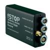
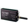
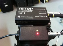
Hi everyone,
We have now finally released our microprocessor controlled C100 / C300 / C500 camera Start / Stop interface.
http://www.plcelectronicsolutions.com/c300-on-off-cable/
http://www.youtube.com/watch?v=LIOx1d49WZY
http://www.youtube.com/watch?v=A4X9sYejHlM
Works with Bartech, Preston, C-Motion remote follow focus systems using your existing 3 pin Fisher Arri Run cables
Uses the 2.5mm Stereo LANC port on the camera to communicate
the camera Run / Stop signal via the onboard microprocessorGreen LED indicates that the cable is connected and that the Camera is PoweredRed LED indicates the camera is Recording and Microprocessor continually checks thecamera status via the LANC protocol to ensure that the camera is running.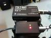
-
J7
in Follow Focus
Hello Faiz
Could you please post a picture of the J7 with the connector.
The issue is most likely a bad cable connection if you do not have either function
working. Likely the Power or Ground connection has broken.
Where are you located?
Most likely there will be an Electronics Technician in your area that can do the repair
Try either a TV or Stereo repair shop.
The repair will probably cost about $40 to $60 if it is just a simple cable issue.
Hope this helps,
Marc
-
Yes,
This is the plan for the future. I have just added them into the
wireless protocol.
Best Regards,
Marc
-
I didn't notice a channel selection for the Iris on the remote. Can multiple of them operate in the same space at the same time? (a 2 camera show for instance)
Also whats the status on zoom control?
The idea of a full FIZ option at such an attractive price point is awesome.
~Jess
Hi Jess,
I wrote the software for the Bartech multi-channel handset upgrades to send Focus and Iris on the same Channel
That way you can have multiple systems on the same set in multi channel mode
The Digital receiver has 16 switch positions to choose from 0-9,a,b,c,d,e,f
0 to 7 are for focus
A = channel 0 iris
B = channel 3 iris
C = channel 7 iris
So when you have a 2 channel Focus /Iris handset you can for example
set the Handset to Channel 0.
on the Focus receiver set the Channel to 0
and on the Iris receiver set the Channel to A
Cheers,
Marc
-
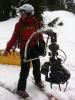
About 3 years ago I got to ski this rig for "The Big Year"
some shots made it also into the Trailer

This was the only time I have ever worn a camera, and I happened
to work part time as a Ski Patrol Medic on the mountain that the show was
filming at so I was approached to ski the rig.
it was good times knowing that at over 25 Mph on an Icy run
and chasing 2 stunt skiers that falling definitely was NOT
an option :blink:
Someone else was operating the camera remotely.
Gladly everything turned out well... this is one day that i did not want to fall :D
-
Hi Robert,
Great to see you again today !!
Here is that antenna:
Preston MDR tranceiver 2.4 GHz Antenna: ANT-2.4-CW-RCS
Marc
-
Hi All,
Several people have called recently that wanted to
get replacement antennas quickly. I have used
Digikey for the past several years as they ship overnight!
I just wanted to post this list of common antennas.
From www.digikey.com
Bartech Handset Transmitter 900 Mhz antenna : ANT-916-CW-QW
Bartech Digital Receiver 900 Mhz antenna: ANT-916-CW-RH
Bartech Analog Receiver 900 Mhz antenna: ANT-916-CW-RH
Link 1 Cini Remote Wireless 900 Mhz antenna: ANT-916-CW-RH
Preston MDR tranceiver 2.4 GHz Antenna: ANT-2.4-CW-RCS
Cheers
Marc
-
The analog Bartech works with the G Zoom. The digital Bartech will not work with the G-Zoom as there is no analog input to the BDR.
The difference between the Analog and Digital Bartech receivers are the types of motors that each work with.
The Analog Bartech works with motors such as the M-One analog and Heden M26P that have a potentiometer that detects the
position on the output shaft of the motor. These motors use a 5 pin Lemo connector.
See this article: Potentiometer
The Digital Bartech works with most industry standard lens motors such as Heden, Preston, Scorpio and M-One Digital. These use
use Digital Optical Shaft Encoders connected to the Motor itself that generate Digital pulses that are used to derive the
position of the output gear of the motor and this is used by the Digital feedback circuit in the receiver to position the motor.
These motors have a 7 pin Lemo connector on them.
Here is a great article: Optical Encoder
Hope this helps,
Marc
-
Hello there,
i have a bartech Remote + Heden M26VE Motor.
Powered by an old (but full)
IPX NP-L 7S via Hirose Plug (4 - pin) to 2 pin Lemo to the control device.
But it does not work.
As long as the motor is not plugged in, everything is fine.
And with motor, no chance... i even can not calibrate....
Any Ideas?
To low power? i guess it´s so.
Hello Patrick,
It is likely that if you are running on 12 volts and the Torque in the BDR is set too high
and the motor is trying to draw too much power from the power supply.
Try lowering the torque
I sent you a PM with contact details
regards,
Marc
-
Do you have numbers for current draw for Preston motors with the BDR?
fSTOP BDR Currents with Preston DM2 motor
12V
Calibrating - Moving 136.5 mA
Calibrating - First stop 231.25 mA
Calibrating - Second stop 279 mA
Motor - not moving 74.88 mA
Motor - moving 163.75 mA
Motor - moving under load 624.75 mA
Motor - stalled 1.29 A
24V
Calibrating - Moving 102.75 mA
Calibrating - First stop 222 mA
Calibrating - Second stop 287.25 mA
Motor - not moving 54.33 mA
Motor - moving 230.5 mA
Motor - moving under load 619.25 mA
Motor - stalled 1.87 A
Regards,
Marc
-
Do you have numbers for current draw for Preston motors with the BDR?
I only have a Preston DM2 motor in the lab at the moment and will work on getting the data
-
Hi All
Alex and I just ran some tests in the Lab to get numbers.
fSTOP BDR with M26Ve Currents
Just to refresh everyone: 1000 mA = 1 Amp
12V
Calibrating - Moving 119.75 mA
Calibrating - First stop 546.25 mA
Calibrating - Second stop 540.75 mA
Motor - not moving 74.76 mA
Motor - moving 134.5 mA
Motor - moving under load 758.13 mA
Motor - stalled 1.38 A
24V
Calibrating - Moving 91.18 mA
Calibrating - First stop 481.79 mA
Calibrating - Second stop 497.17 mA
Motor - not moving 51.22 mA
Motor - moving 164.88 mA
Motor - moving under load 799.88 mA
Motor - stalled 2.55 A
Cheers,
Marc
-
I just bought myself a Bartech with the digital receiver and Preston motor. The BDR and handset and cables would cost you far less than $5k. I chose to go the digital route because it future proofs my investment...if in the (distant) future I want to upgrade to a Preston, I've already got the motor and motor cables! Plus, I'd still have the Bartech as a backup.
So the cables are the same pinouts on the BDR as the MDR2? Is that the same for Run/Stop and Power also? ...Jim???
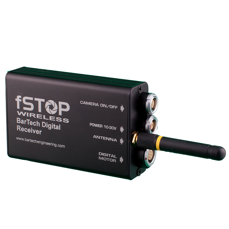
Alfeo,
The motor connection on the BDR is the same 7 pin Lemo shell size 1B as used on the MDR2, Scorpio, C-Motion.
The wiring is also the same.
The power for the BDR is a 2 pin Lemo shell size 0B which is the standard that the Bartech analog receivers use.
The camera on/off is a 4 pin Lemo shell size 0S which is also the standard from the Bartech analog receivers.
Here are some images
Regards,
Marc
www.plcelectronicsolutions.com
-
I believe that Jim is in contact with Don.
Try reaching him at
jim@bartechengineering.com
Don's new info ( from a previous post )
Here are his new contact details:
e-mail: don@loonworks.com
tel: 406-837-1370
address: 439 Grand Dr., Suite 191
Bigfork, MT 59911
Regards,
Marc
-
-
Hi Ben
We just posted this info on our website yesterday with pictures of the motors
We now distribute Heden and carry stock of the M21VE and M26VE
HEDÉN M21VE SPECIFICATIONS:
Weight: 155 g / 5 1/2 ozs
Length: 97 mm / 3.82 inches
Width: 21 mm / 0.83 inches
Height: 28 mm / 1.1 inches
Torque (Max): 0.7 Nm
Connector: LEMO size 1 7-pin
HEDÉN M26VE SPECIFICATIONS:
Weight: 250 g / 7.70 ozs
Length: 120 mm / 4.72 inches
Width: 26 mm / 1.02 inches
Height: 33 mm / 1.29 inches
Torque (Max): 1.90 Nm
Connector: LEMO size 1 7-pin
-
No Problem Alan
Did you get it fixed yet?
Hope to see you at NAB
Marc
-
Hello Alan,
If the motor does not chatter it is most likely not an issue with the potentiometer itself.
Based on the symptoms you are decsribing it is likely that the friction clutch that transfers the motor output gear postion to the potentiometer
needs to be tightend.
The way these and most other analog motors work is that they have a motor with a gearbox attached and on the output side of that gearbox
There is a potentiometer that provides an analog output that represents the output position of the motor gear. Most of these potentiometers can only do one full rotation ( some 3 rotations ) and thus they need to have mechanical endstops that prevent the potentiometer from "rolling over " and thus confusing the control system as to which direction the motor just moved. The large amount of torque available on the output side of the gearbox is more than enough to break the endstops on the potentiometer thus manufactures employ a friction clutch.
As long as the friction clutch is tight the potentiometer will accurately track the output gear of the motor. When the clutch slips Before the potentiometer reaches it's endstop it will no longer track accurately ........ Thus causing "drift"
Hopefully this explaination will assist you in being able to service the motor yourself as I do not know of anyone that services these motors
Regards
Marc
-- excuse the spelling on my iPad


FMG 6 motor chatering problems
in Follow Focus
Posted
"Hello everyone ! from the Canary Islands,
Can anyone that has experience changing out the internal potentiometer in a FMG.6 motor help me out with the method of doing it.
Thank you very much in advance."
Jim ?